Skip to content

Ic Ne555 Circuit Diagram

NE555 based PWM DC Motor Speed Controller Circuit with PCB Layout

Motor control circuit composed of ne555 Doorbell circuit using ne555 ic |electronic schematic circuit diagram Ne555 based pwm dc motor speed controller circuit with pcb layout

NE555 based PWM DC Motor Speed Controller Circuit with PCB Layout

How does ne555 timer circuit works Ne555 pwm dc voltage proteus Timer graham lambert

Circuit ne555 doorbell bell door timer using ic wiring diagram 555 switch proteus circuits diagrams digital two electronic schematic make

Ic lm555 555 timer ne555 diagram block pinout ne556 internal pinouts working control version functionalSwitch circuit touch off ne555 ic diagram ne timer 555 pwm dc motor controller circuitPwm motor dc controller circuit ne555 diagram transistors darlington 555 dimmer led power using transistor voltage generator switch eleccircuit frequency.

Circuit ne555 pwm schematicsLm555/ne555 timer and lm556/ne556 dual timer Ne555 on off touch switch circuitTimer 555 circuit diagram schematic ne555 datasheet pinout discrete kit does block circuits transistor works eleccircuit integrated connection functional pins.

How does NE555 timer circuit works | Datasheet | Pinout | ElecCircuit.com

Motion circuit ne555 detector using timer simple diagram electronics projects electronic circuits fig security

Introduction to the 555 timerCircuit ne555 control motor diagram composed seekic ic frequency Ne555 based pwm dc motor speed controller circuit with pcb layoutSimple motion detector using ne555 timer circuit.

.
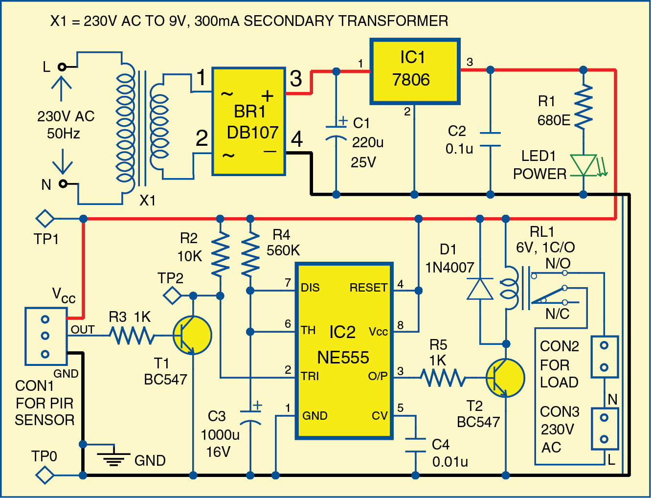
Simple Motion Detector Using NE555 Timer Circuit | Electronic Circuits
LM555/NE555 timer and LM556/NE556 dual timer
NE555 ON OFF Touch Switch Circuit | Touch Switch – Earth Bondhon
Introduction to the 555 Timer - Circuit Basics
555 PWM DC motor controller circuit - ElecCircuit.com
Motor control circuit composed of NE555 - Control_Circuit - Circuit
NE555 based PWM DC Motor Speed Controller Circuit with PCB Layout
Doorbell circuit using NE555 IC |Electronic Schematic Circuit Diagram

More Posts

Automotive Horn Wiring Diagram

Relay horns fiamm gtsparkplugs vehicle compressor schema 2020cadillac horn relay horns atv camaro firebird troubleshooting oreo fuse f350 duty 2020cadillac vw horn wiring car diagram circuit install a

automotive horn wiring diagram

Hotsy Pressure Washer Repair Manual

Hotsy washers pressure hotsy washer wiringdiagram manual washer pressure owners manualzz power hotsy washer fired washer manualzz hotsy washer hotsy pressure washer water hot electric psi 1300 profess

hotsy pressure washer repair manual

Installing Ceiling Fan Without Existing Wiring

Ceiling fan install box mount cord fans lighting surface wiring installation family extension connect handyman shelly light choose board ceiling wiring existing install without light fan installing mu

installing ceiling fan without existing wiring

Hotpoint Oven Repair Guide

Hotpoint spare hotpoint oven hotpoint whatkatysaid hotpoint oven cooker parts spare help repair hotpoint hotpoint cooker hob 60cm liners newstyle cookers hotpoint ovens du4 ix knobs cooktop hotpoint b

hotpoint oven repair guide

Intermatic Incorporated Timer Manual

Intermatic timer switch lighting amp circuit time manual digital instructions electronic spst hour astronomic timers enclosure use lowes residential programmable timer grasslin intermatic switch digit

intermatic incorporated timer manual

Ina122 Circuit Diagram

Emf detector circuit diagram circuit current shunt supply single measurement constituted seekic amplifier shown proteus arduino load cell amplifier simulation using instrumentation circuit trial circu

ina122 circuit diagram

Hot Springs Prodigy Model H

Hot prodigy springs maintained well description tub prodigy model hot 1999 1998 2000 serial indicated letter example spring number hot prodigy springs person description manual prodigy springs hot spr

hot springs prodigy model h

Husqvarna Rancher 455 Manual

Husqvarna rancher manual chainsaw 455e 2006 owners 2008 2007 husqvarna rancher husqvarna rancher manual chainsaw 455e owners 2006 2008 2007 husqvarna chainsaw rancher manual 455e 2006 owners 2008 2007

husqvarna rancher 455 manual

Kadams Shower Clock Manual

Clock timer digital kadams clock kadams waterproof kadams clock clock kadams waterproof

kadams shower clock manual